RAD242

Features
- Remote intelligent A/D I/O unit with opto-isolated RS-485 interface to host computer
- NEMA 4 enclosure for harsh atmospheric and marine environments
- Type 8031 microcontroller with 32K x 8 bits RAM and 32K x 8 bits EEPROM.
- Two-channel 24-bit A/D delta-sigma converter
- Bi-polar and unipolar voltage input ranges of 2.5 V and 5 V
- Self-calibrating or auto-calibrating modes to eliminate drift errors
- 13-bit digital port with each bit programmable as either input or output
- Constant current source for thermocouple cold-junction compensation
- Precision 10 VDC excitation for transducers
- All programming in software, almost no switches.
- Designed, made, supported, and manufactured in the USA
$450.00
In StockDescription
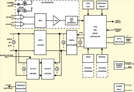
Model RAD242 is an intelligent, two-differential-channel, 24-bit analog-input interface unit that includes a Delta-Sigma A/D converter. The converter has a digital output filter with adjustable notch frequency from 10 Hz to 2000 Hz. The pod also has 13 bits of digital input/output. A precision 10 VDC voltage that can be used for transducer excitation is available at connector pin 5. As much as 60 mA current can be provided. It is packaged in a NEMA 4 enclosure for remote installation in harsh environments. RAD242 also provides a user-definable interrupt input and counter/timer input. An optional RAD Firmware Development Kit is available if you wish to use those user-programmable input lines or to develop a custom program.
A built-in watchdog timer resets the pod if, for some unexpected reason, the microcontroller “hangs up” or if the power supply voltage drops below 4.75 VDC. Data collected by the pod is stored in local RAM for later access through the computer’s serial port. This feature facilitates a stand-alone mode of operation. For example, a portable or laptop computer that has an RS-485 port can be brought to the pod, connected, and collect the data.
APPLICATIONS
RAD242 is useful for wide dynamic range measurement of low-voltage analog signals. Typical applications include strain-gage weight measurements and precision thermometry. With the addition of the rugged enclosure and built-in intelligence, the RAD242 is ideal for process control, plant monitoring, and HVAC applications. RAD242’s design is optimized to perform readings on channel 0 with occasional readings on channel 1. This is admirably suited for thermocouple temperature measurements with the cold-junction reference attached to channel 1. In the case of sensors connected in a bridge, channel 1 can be used to monitor the excitation voltage or current in order to perform a ratiometric measurement.
BREAK DETECTION
There is a switchable current source on analog channel 0 that may be used to detect a burned-out or disconnected external sensor. This current source may be used to check that a sensor is OK before taking measurements from that sensor.
TRANSDUCER EXCITATION VOLTAGE
RAD242 includes a source for a precision 10 VDC that can be used to excite sensors such as strain gage load cells, pressure transducers, etc. As much as 60 mA current can be provided.
DELTA-SIGMA CONVERTER
Model RAD242 uses a Delta-Sigma analog-to-digital converter and provides exceptional noise, linearity, and resolution characteristics. Delta-Sigma converters are fundamentally different from other converter technologies. Traditional A/D designs are based on high-accuracy analog components like resistors and comparators to provide reliable conversions. But analog circuits are subject to drift due to temperature and aging effects. Delta-Sigma converters are almost entirely digital and avoid many of the problems of analog circuits.
A delta-sigma converter consists of a sample/hold amplifier, a differential amplifier (subtractor, the delta part), an analog low-pass filter (integrator, the sigma part), a comparator, a 1-bit DAC, and a digital filter. The analog signal is applied to the subtractor along with the output of the l-Bit DAC. The subtractor output is applied to the low-pass filter and the low-pass-filtered output is, in turn, coupled to the comparator. The comparator output is samples of the difference signal at a frequency many times the Nyquist frequency. (The Nyquist frequency is equal to 2X the highest frequency present in the analog signal.) This process is called oversampling.
The delta-sigma converter in RAD242 samples the analog signal at 19.5 KHz or greater (depending on the gain selected). As a result, the quantization noise is spread over a wider frequency than the band of interest. The noise in the band of interest is reduced further by the low frequency filter. The output of the comparator provides the digital input to the 1-Bit DAC so that the system functions as a negative feedback loop that tries to minimize the difference signal. The digital data that represents the analog input voltage is contained in the duty cycle of the pulse train appearing at the output of the comparator. If the analog signal is zero, the duty cycle is 50%. The duty cycle increases for a positive analog signal and decreases for a negative one. The digital filter removes noise injected during the conversion process. The output of the digital filter is a binary representation of the rolling average of the sampled signal.
This architecture is inherently monotonic (no missing codes) and provides very high accuracy but at the expense of measurement speed (data output rate). For example, to achieve 22 bits resolution, a 10 MHz clock rate would result in a data or measurement rate of less than 10 Hz. The processes of oversampling and then integrating the readings produces a fixed delay from the time that an analog sample is taken until the digital value is output. The amount of delay is dependent on the oversampling rate. In most signal processing applications this lag is not significant. However, for real-time control applications, this lag should be considered.
CALIBRATION
Despite the use of inherently stable delta-sigma converters with low-drift components an occasional calibration may be necessary. Calibration removes offset and gain errors due to the effects of temperature drift, supply changes, zero drift, and full scale gain errors. A calibration routine may be required whenever there is a significant change in the ambient operating temperature or supply voltage. It should also be initiated if there is a change in the selected channel gain, filter notch or bipolar/unipolar input range.
Calibration of RAD242 can be done in any of three ways:
a. System calibration.
b. Self calibration of the A/D.
c. Background calibration of the A/D.
System calibration requires application of zero volts and full-scale voltage to the pod’s analog inputs. Self calibration of the A/D chip can be performed in software and uses the reference voltage. Background calibration of the A/D can be commanded in software to occur with each conversion. In the background-calibration mode, the calibration procedure is interleaved with the normal conversion sequence and reduces the conversion rate by a factor of six. Calibration constants are stored automatically in the EEPROM.
PROGRAMMABLE DIGITAL FILTER
The internal digital filter removes noise added during the conversion and sums the oversampled readings to produce multiple bit measurements at a data update rate determined by the first notch of the digital filter. Internally, the converter provides measurements at a 19.5 KHz output rate and the data is filtered down to the update rate defined by the digital filter. Post filtering may be used to increase the update rate or to reduce output noise. For example, if the bandwidth is 7.86 Hz at the desired resolution (resulting in an update rate of 30 Hz) but the desired update rate is 100 Hz, the data could be taken at the 100 Hz rate and filtered down to the 7.86 Hz bandwidth to achieve the same accuracy.
Post filtering can also be used to reduce the output noise for bandwidths below 2.62 Hz. At a gain of 128, the output RMS noise is 250 nV. This is essentially device noise or white noise, and since the converter uses a chopper-stabilized input stage to reduce input drift, the noise has a flat frequency response. By reducing the bandwidth below 2.62 Hz, the noise in the resultant passband can be reduced. A reduction in bandwidth by a factor of two results in a reduction in the output rms noise equal to the square root of two. This additional filtering will also result in a longer settling time.
The worst-case settling time of the filter for a full-scale step input change is four times the data rate. For example, with the first filter notch at 50 Hz, the full-scale step settling time of the filter would be 80 mS (maximum). Due to a digital signal processing method used by the delta-sigma converter in the RAD242, changing the channel gain (in addition to the output sample rate) impacts the resolution.
DIGITAL INPUTS/OUTPUTS
In addition to the analog input channels, RAD242 has 13 bits of bidirectional digital input/output bits. In the output mode, there is high current-sink capacity (350 mA) and the open-collector outputs can be connected to external voltage sources of up to 50 V. If no external source is used then each I/O bit is pulled up to +5 VDC.
Downloads
Manuals
Drivers and Downloads
Full list of available Downloads: Software Packages, Drivers, Manuals, and other documents
Information about our Free Software packages:
ACCES is proud to provide a full suite of software support with every Data Acquisition product. We are committed to supporting the most popular operating systems and platforms for our customers. Currently we are actively supporting XP -> 10, both 32 & 64 bit, including “Server 2008,” “Embedded,” and “Compact” flavors for all plug-and-play products including PCI, PCI Express, USB, and more. Many products continue to ship with support for additional operating systems such as DOS, Windows 95, 98, Me, NT4, and 2000.
Samples
Among the software we deliver with our products are sample programs in a wide variety of programming languages. These samples are used to demonstrate the software interfaces to our products — and many can be used as-is in your production environments, or to test functionality of the devices out-of-the-box. We’re currently actively supporting sample programs in Microsoft Visual C#, Visual Basic, Delphi, and Visual C/C++, with many devices including samples in Borland C/C++ 3.1 for DOS. Additionally we provide National Instruments LabVIEW compatible DLLs and many demonstration VIs for our devices.
Drivers
Drivers for various operating systems are also provided, including active support for Windows XP -> 10 — all in both 32-bit and 64-bit flavors, and including consumer, server, and embedded varieties — as well as the 2.6 and newer Linux kernels and recent OSX / macOS versions. Many products continue to ship with driver support for Windows 95, 98, Me, NT4, and Windows 2000, but support for these operating systems is considered deprecated.
Setup Programs and Utilites
Our Data Acquisition devices also include a graphical setup utility that walks you through the process of configuring any option jumpers or switches on the device, as well as explaining a little about the various connectors present.
Many devices also include utility programs – little tools to make your use of the device easier, such as EWriter, a program that allows you to read and write data in the user-accessible EEPROM locations on all our USB data acquisitition products; or WinRISC, a “Really Incredibly Simple Communications” terminal program that lets you get started instantly with serial devices.
“Register Level” Documentation
Besides all this software in all these languages and operating systems ACCES has a policy of open and transparent development: none of our lowest-level “register” interfaces are hidden from you — we document every register in every bus card, every command in every serial board, and every usb control transfer in every USB Data Acquisition board. These lowest-level interfaces allow you to develop for our products in ANY operating system or language, regardless of our actively supporting it or having a driver for it. We have customers actively developing in ADA, Android, Python, Java, MATLAB, Solaris, and more, just by referring to our complete low-level interface documentation! And we provide the full source code to all of our drivers, regardless of operating system, to give you an even bigger head start in your own development tasks.
No Fees or Royalties
All of this software is provided at no additional charge, and is licensed under any of a variety of flexible — and royalty free — options. Check out our software license explanation if you’d like more information.
Custom Software
ACCES also offers Custom Software Services for our products. Our prices are unbelievably low, often as inexpensive as free! If you need something tweaked to support your needs, or an entire enterprise application developed from scratch, it is definitely worth your time to inquire with us, first.
Further information about available ACCES Software:
Redistributing Windows Drivers
A list of ACCES drivers and the files that compose them under different versions of Windows, so you can easily redistribute ACCES cards and drivers.
Analog Input
- Channels: 2 Differential.
- Data Coding: Binary for Unipolar inputs, Offset Binary for Bipolar inputs.
- Resolution: Dependent on filter frequency.
- Input Voltage Range: Software selectable, 0 – 2.5V and ±2.5V or, if jumper is used to select +5 VDC reference, 0-5V and ±5V.
- Input Impedance: 1 Gigohm at DC. Varies with input sample rate.
- Programmable Gains: 1, 2, 4, 8, 16, 32, 64, and 128.
- Overvoltage: Continuous single channel, to ±35V without damage.
- DC Input Leakage Current: @25°C, 10 pA max.
- Temp. Coefficient: Due to the thermal mass of the NEMA enclosure and internal heating by the power supply regulators, the pod reacts very slowly to any ambient temperature changes. Further, automatic re-calibration or background calibration can be used to remove temperature errors.
- Integral Nonlinearity: @ 25°C: ±0.0015% of Full Scale Reading max.
TMIN to TMAX: ±0.0075% of FSR typical. - Common Mode Rejection Ratio: 100 dB min., at DC.
- Normal Mode Rejection at 60 Hz: 100 dB ±0.02 x ƒ NOTCH min., for ƒNOTCH, of 10, 30, 60 Hz.
- Common Mode Rejection at 60 Hz: 150 dB ±0.02 x ƒNOTCH min., for ƒNOTCH of 10,30, 60 Hz.
Analog Outputs
- Compensation Current: 20µA nom., constant current source for thermocouple cold junction reference measurements.
- Transducer Test Current: 4.5µA nom., switchable current source tied to the positive input lead of analog channel one to test the existence/ operation of any external sensor.
- Transducer Excitation: Precision 10 VDC (±0.01V) at up to 60 mA.
Digital Inputs
- Number: Thirteen, on same pins as the output bits, each bit is individually programmable as either an input or output bit.
- Sample Rate: Ports must be polled to read data.
- Logic Input Low: -0.5V to +0.8V.
- Logic Input High: +2.0V to +50.0V.
- Low-Level Input Current: -450 µA maximum.
Digital Outputs
- Number: Thirteen, on same pins as the input bits, each bit is individually programmable as either an input or output bit.
- Logic-Low Output Current: 350 mA maximum. Inductive suppression diode included in each circuit.
- High-Level Output Voltage: Open collector, compliance with up to 50V user supplied voltage. If no user supplied voltage, outputs pulled up to +5VDC via 10 KW resistors.
Environmental
- Operating Temperature Range: 0° to 65°C (Optional -40° to +80°)
(For Temperature De-rating considerations, refer to the “Temperature De-rating” discussion in the REMOTE ACCES Overview page that presents “Specifications common to all REMOTE ACCES pods.”) - Storage Temperature Range: -50°C to +l20°C.
- Humidity: 5% to 95% RH non-condensing. Enclosure is designed to meet NEMA 4 requirements.
Power Required
- Power for the opto-isolated section can be applied from the computer’s +12 VDC power supply via the serial communications cable or by an isolated local power supply. Power for the rest of the pod can be provided by a local power supply.
- Opto-lsolated Section: 7.5 to 23 VDC @ 40 mA maximum (7 mA at 12 VDC).
- Local Power: 10.5 to 16 VDC at 150 mA plus transducer excitation current used, if any. Also, note that the unit can be used with local power as low as 7.5 VDC but the 10 VDC excitation voltage and the +5 VDC reference voltage will not be available.
| Model | Description | Price (USD) | |
|---|---|---|---|
| RAD242 | Model RAD242 is an intelligent, two-differential-channel, 24-bit analog-input interface unit that includes a Delta-Sigma A/D converter. The converter has a digital output filter with adjustable notch frequency from 10 Hz to 2000 Hz. The pod also has 13 bits of digital input/output. A precision 10 VDC voltage that can be used for transducer excitation is available at connector pin 5. As much as 60 mA current can be provided. It is packaged in a NEMA 4 enclosure for remote installation in harsh environments. RAD242 also provides a user-definable interrupt input and counter/timer input. An optional RAD Firmware Development Kit is available if you wish to use those user-programmable input lines or to develop a custom program. A built-in watchdog timer resets the pod if, for some unexpected reason, the microcontroller “hangs up” or if the power supply voltage drops below 4.75 VDC. Data collected by the pod is stored in local RAM for later access through the computer’s serial port. This feature facilitates a stand-alone mode of operation. For example, a portable or laptop computer that has an RS-485 port can be brought to the pod, connected, and collect the data. APPLICATIONSRAD242 is useful for wide dynamic range measurement of low-voltage analog signals. Typical applications include strain-gage weight measurements and precision thermometry. With the addition of the rugged enclosure and built-in intelligence, the RAD242 is ideal for process control, plant monitoring, and HVAC applications. RAD242’s design is optimized to perform readings on channel 0 with occasional readings on channel 1. This is admirably suited for thermocouple temperature measurements with the cold-junction reference attached to channel 1. In the case of sensors connected in a bridge, channel 1 can be used to monitor the excitation voltage or current in order to perform a ratiometric measurement. BREAK DETECTIONThere is a switchable current source on analog channel 0 that may be used to detect a burned-out or disconnected external sensor. This current source may be used to check that a sensor is OK before taking measurements from that sensor. TRANSDUCER EXCITATION VOLTAGERAD242 includes a source for a precision 10 VDC that can be used to excite sensors such as strain gage load cells, pressure transducers, etc. As much as 60 mA current can be provided. DELTA-SIGMA CONVERTERModel RAD242 uses a Delta-Sigma analog-to-digital converter and provides exceptional noise, linearity, and resolution characteristics. Delta-Sigma converters are fundamentally different from other converter technologies. Traditional A/D designs are based on high-accuracy analog components like resistors and comparators to provide reliable conversions. But analog circuits are subject to drift due to temperature and aging effects. Delta-Sigma converters are almost entirely digital and avoid many of the problems of analog circuits. A delta-sigma converter consists of a sample/hold amplifier, a differential amplifier (subtractor, the delta part), an analog low-pass filter (integrator, the sigma part), a comparator, a 1-bit DAC, and a digital filter. The analog signal is applied to the subtractor along with the output of the l-Bit DAC. The subtractor output is applied to the low-pass filter and the low-pass-filtered output is, in turn, coupled to the comparator. The comparator output is samples of the difference signal at a frequency many times the Nyquist frequency. (The Nyquist frequency is equal to 2X the highest frequency present in the analog signal.) This process is called oversampling. The delta-sigma converter in RAD242 samples the analog signal at 19.5 KHz or greater (depending on the gain selected). As a result, the quantization noise is spread over a wider frequency than the band of interest. The noise in the band of interest is reduced further by the low frequency filter. The output of the comparator provides the digital input to the 1-Bit DAC so that the system functions as a negative feedback loop that tries to minimize the difference signal. The digital data that represents the analog input voltage is contained in the duty cycle of the pulse train appearing at the output of the comparator. If the analog signal is zero, the duty cycle is 50%. The duty cycle increases for a positive analog signal and decreases for a negative one. The digital filter removes noise injected during the conversion process. The output of the digital filter is a binary representation of the rolling average of the sampled signal. This architecture is inherently monotonic (no missing codes) and provides very high accuracy but at the expense of measurement speed (data output rate). For example, to achieve 22 bits resolution, a 10 MHz clock rate would result in a data or measurement rate of less than 10 Hz. The processes of oversampling and then integrating the readings produces a fixed delay from the time that an analog sample is taken until the digital value is output. The amount of delay is dependent on the oversampling rate. In most signal processing applications this lag is not significant. However, for real-time control applications, this lag should be considered. CALIBRATIONDespite the use of inherently stable delta-sigma converters with low-drift components an occasional calibration may be necessary. Calibration removes offset and gain errors due to the effects of temperature drift, supply changes, zero drift, and full scale gain errors. A calibration routine may be required whenever there is a significant change in the ambient operating temperature or supply voltage. It should also be initiated if there is a change in the selected channel gain, filter notch or bipolar/unipolar input range. Calibration of RAD242 can be done in any of three ways: a. System calibration. System calibration requires application of zero volts and full-scale voltage to the pod’s analog inputs. Self calibration of the A/D chip can be performed in software and uses the reference voltage. Background calibration of the A/D can be commanded in software to occur with each conversion. In the background-calibration mode, the calibration procedure is interleaved with the normal conversion sequence and reduces the conversion rate by a factor of six. Calibration constants are stored automatically in the EEPROM. PROGRAMMABLE DIGITAL FILTERThe internal digital filter removes noise added during the conversion and sums the oversampled readings to produce multiple bit measurements at a data update rate determined by the first notch of the digital filter. Internally, the converter provides measurements at a 19.5 KHz output rate and the data is filtered down to the update rate defined by the digital filter. Post filtering may be used to increase the update rate or to reduce output noise. For example, if the bandwidth is 7.86 Hz at the desired resolution (resulting in an update rate of 30 Hz) but the desired update rate is 100 Hz, the data could be taken at the 100 Hz rate and filtered down to the 7.86 Hz bandwidth to achieve the same accuracy. Post filtering can also be used to reduce the output noise for bandwidths below 2.62 Hz. At a gain of 128, the output RMS noise is 250 nV. This is essentially device noise or white noise, and since the converter uses a chopper-stabilized input stage to reduce input drift, the noise has a flat frequency response. By reducing the bandwidth below 2.62 Hz, the noise in the resultant passband can be reduced. A reduction in bandwidth by a factor of two results in a reduction in the output rms noise equal to the square root of two. This additional filtering will also result in a longer settling time. The worst-case settling time of the filter for a full-scale step input change is four times the data rate. For example, with the first filter notch at 50 Hz, the full-scale step settling time of the filter would be 80 mS (maximum). Due to a digital signal processing method used by the delta-sigma converter in the RAD242, changing the channel gain (in addition to the output sample rate) impacts the resolution. DIGITAL INPUTS/OUTPUTSIn addition to the analog input channels, RAD242 has 13 bits of bidirectional digital input/output bits. In the output mode, there is high current-sink capacity (350 mA) and the open-collector outputs can be connected to external voltage sources of up to 50 V. If no external source is used then each I/O bit is pulled up to +5 VDC. | $450.00 |