source: Wikipedia
No matter if you’re an engineer or a rather average computer user, USB’s logo is probably almost as familiar to you as that of Apple. USB communication has established a standard in the industry of PCs and embedded systems with billions of USB products shipped every year. Truth be told, at this point, its popularity alone is often enough to make it the best solution for many applications, but this is not everything that this communication technology has to offer. In this column, we’ll ponder over what USB is and what in particular makes it so special, what are its shortcomings and finally when you should consider using USB in your embedded systems. To better understand how this technology became so ubiquitous in the tech industry it will be useful to look at how it came into existence.
Back in the 1980s and early 1990s, connecting devices was much more troublesome than it is now. Peripherals utilized a variety of interfacing methods, required manual installation of drivers and different cables and the control unit had to have the hardware or an expansion card prepared specifically for them. For example, set up of a device tree for IBM Personal Computer required a dedicated keyboard that would use a 5 pin DIN socket which was the only connection with a direct access to the motherboard. For all other peripherals, there were expansion cards that you had to plug into the special ISA slots on the motherboard: video card for a monitor, game control adapter for a joystick, IBM Asynchronous Adapter (serial port card) for various types of HIDs and a parallel port card. If that wasn’t inconvenient enough, other manufacturers used different ports and coming across devices dedicated to being compatible with only one machine was not uncommon.
Driven by the desire to simplify the process of interfacing devices with the host, in 1994, a group of 7 tech giants at the time: Compaq, IBM, Intel, NEC, Microsoft, Nortel, and Digital decided to collaborate on the creation of a new, universal, easy to use, fast and multifunctional connection interface. The development of what they named Universal Serial Bus took a little over a year of work and in January 1996 the USB 1.0 has left Intel Labs and was introduced to the world. As promised, the new communication protocol met all of the original requirements and included few additional perks that made it even easier to interface peripheral devices with the computer:
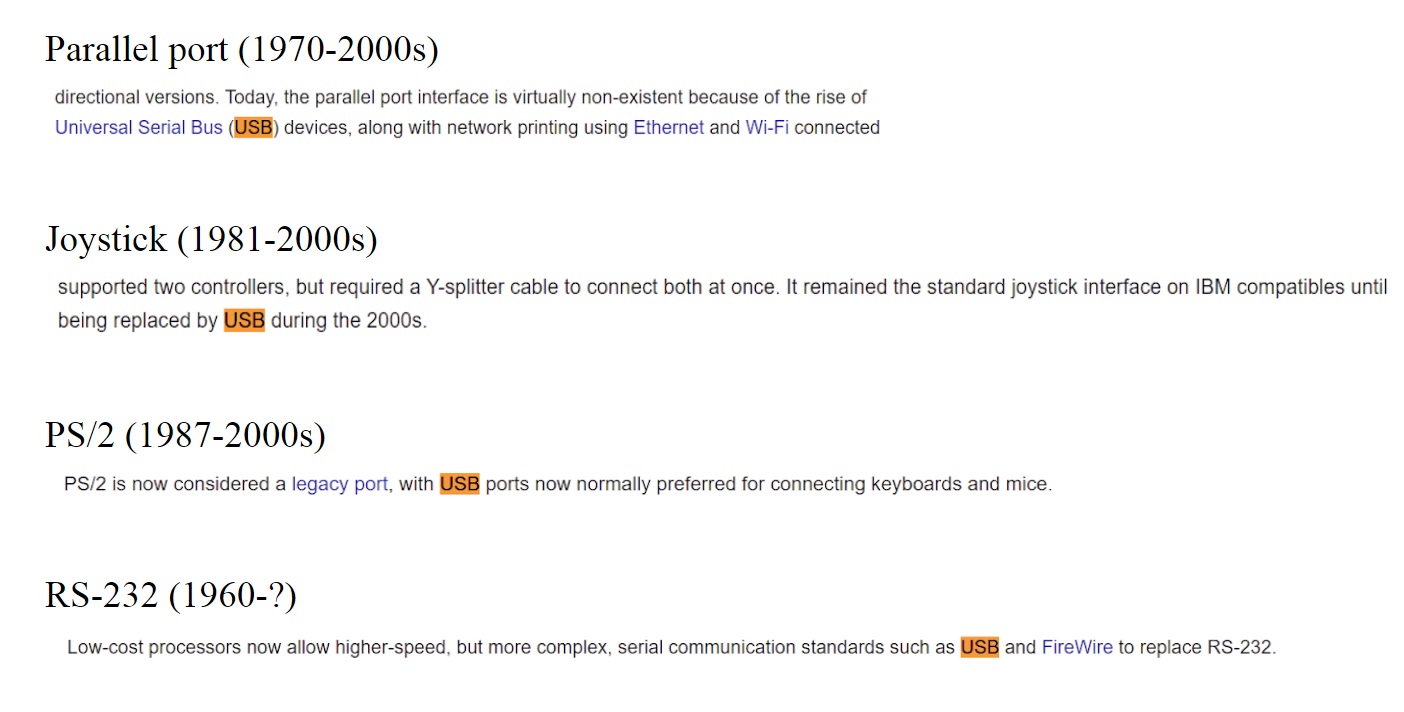
Introduction of USB technology has created a paradigm shift in terms of being user-friendly making connecting devices foolproof and effortless even for the most inexperienced users. It allowed for connecting virtually any type of device from printers and external hard drives to webcams and game controllers to keyboards, smartphones, and mice. That’s how the troublesome and tedious process of setting up a device tree turned into plugging the cable into one of the USB ports in the host system. As a logical consequence of that, a lot of traditional solutions were fully or partially superseded letting USB establish as a standard in communication protocols.
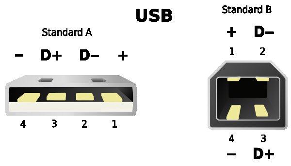
USB, like most other cables, has two ends. Type A (on the left), is designed for host devices and for increased compatibility almost always takes on the form shown in the diagram. Type B (on the right) is usually used for control of the peripherals and the shape and size of connectors can vary depending on the needs of a particular device. Inside of a traditional USB 2.0 cable, there are 4 shielded wires. Two of them are power (1) and ground (4) that allow the device to be powered by the host through the USB connection, eliminating the need for an additional power supply. The other two wires, the data upstream (3) and data downstream (2) are responsible for the transmission of the data, which is streamed in a form of a differential signal. Typically for this type of signaling, they are wired to form a twisted pair for reduced electromagnetic radiation and crosstalk between neighboring pairs.
In USB architecture, there will always be a host and a device connected to it. Their model of communication is often referred to as a master-slave relationship. The PC or the primary embedded system is the master and it controls all of the communications on the bus. Since USB is a serial type connection it can communicate with one device at a time and one of the master’s tasks is to tell slaves when it is their turn to exchange the data with him. USB specification allows for up to 127 devices to be connected to one host port in a tiered, star topology with a limit of up to 7 tiers (host + 5 hubs + device). Implementing this type of topology where the hub acts as a middleman that provides an additional power source ensures enough power supply for every connected device.
Data transmission in USB connection doesn’t have an external clock line (asynchronous), which enables it to send information at different speeds. Because the host communicates with only one device at a time and devices send the data at different rates, hubs also play an important role in data transmission. They can help with data trafficking on the bus by retransmitting the data from slower devices at the highest speed, freeing the bandwidth for other connections.
When you see that your device utilizes a USB connector, you already know that you don’t have to know a single thing more about the host or a device to connect them properly. That’s because USB has a plug and play feature which enables the host to access basic information about the device, assign it with a unique address and load one of the appropriate drivers stored in host’s OS onto it. In the case when the devices are using custom drivers that are not included in the standard OS package, they can be found online (accesio.com > Drivers & Downloads) or in installation packets that come with the device.
There is also no need to turn off the host system (which is how it used to be) before plugging in the USB device because the connection is hot-pluggable. In desktop PCs, this could make little of a difference, but sure enough, it is convenient. However, when it comes to heavy-duty machinery, medical apparatus, or military equipment, where shutting down the system can be expensive or even life-threatening this feature really shows its potential. It allows broken components to be replaced with little to no effect on the whole system, minimalizing the mean time to repair. Before USB, connecting a device while the system was running could damage the device, the host or in some cases both. That’s the reason why most of the old connectors had to have safety measures like screws preventing peripherals to be unintentionally detached.
Another important feature of USB is the support of full backward compatibility, meaning that all USB devices, no matter what generation of this technology the host or the peripheral uses, will work just fine with one another. You can essentially plug your USB 1.1 I/O device from 1998 into the 3.2 port in your new computer and it will run the same software apps without the need for any modifications. This means that while this technology is constantly being developed, there is no need to worry about the lifespan USB may have.
USB was originally designed to interface peripheral devices to desktop PCs and for a few reasons, it wasn’t suitable for use in an industrial environment which is why initially it didn’t seem to be an attractive alternative to other buses used in the Data Acquisition and Control market. After addressing these issues, however, advantages of USB became clearer and it started slowly earning its place and recognition in the world of embedded systems. Below is an overview of advantages and limitations for a typical USB connection and a brief discussion of solutions to the most common problems with this technology in embedded systems applications.
|
USB 1.0 |
1.5Mb/s LowSpeed |
|
12 Mb/s FullSpeed |
|
|
USB 2.0 |
480 Mb/s HighSpeed |
|
USB 3.0 |
5 Gb/s SuperSpeed |
|
USB 3.1 |
10 Gb/s SuperSpeed+ |
|
USB 3.2 |
20 Gb/s SuperSpeed+ |
In general, USB is considered not ideal for closed-loop control applications, however, when the closed loop output is for example to flip the switch (~ 5ms) the latency of 0.25ms doesn’t make any noticeable difference. This limitation of USB is more visible when the closed loop works with higher frequencies like in audio noise canceling or laser intensity adjustment. Internal buses like PCI Express or Mini PCI Express are generally better for these types of applications.
USB has quickly won hearts of users of desktop PCs and small consumer devices, but there is a lot of ways in which this technology had to be adapted before it earned its spot in the DAQ market. USB is notoriously cheap and delicate but when it’s made in the right way, it becomes a very reliable bus.
In Data Acquisition and Control market, most customers don’t need a bandwidth higher than 20 Mbs so the constantly improving transfer speeds of new USB buses are irrelevant for the majority of applications. The more important transaction rate, on the other hand, stays virtually the same for new generations which doesn’t give too much incentive for DAQ industry to upgrade to higher versions. Additionally, the full backward compatibility of USB ensures that the devices won’t get outdated and left incompatible. With that forward proofing, even though the bandwidth is getting better, USB 3 is more expensive while still having similar frequency, rendering it excessive for a low bandwidth market.
 by Marcin Kierebinski, Mechanical and Elecrical Engineering intern at ACCES I/O.
Marcin Kierebinski is our awesome Mechanical and Electrical Engineering intern that currently studies at University of California, San Diego. His project experience in Embedded Systems involves utilizing inertial measurement units (IMUs) for portable motion capture applications.